XBee/XBeePRO"燨EM燫F燤odules??02.15.4?爒1.xAx燵2007.05.031]
2007燤axStream,營nc.
牋牋?
Chapter??燲Bee/XBeePRO燨EM燫F燤odules
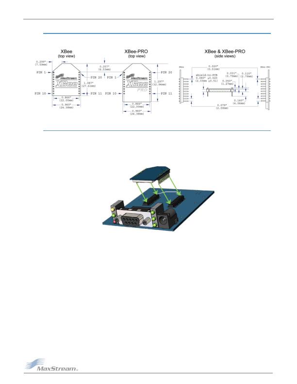
1.3. Mechanical Drawings
Figure?01. Mechanical燿rawings爋f爐he燲Bee/XBeePRO燨EM燫F燤odules?antenna爋ptions爊ot爏hown)
The燲Bee燼nd燲BeePRO燫F燤odules燼re爌inforpin燾ompatible.?/SPAN>
1.4. Mounting Considerations
The XBee/XBee-PRO RF Module was designed to mount into a receptacle (socket) and therefore
does not require any soldering when mounting it to a board. The XBee Development Kits contain
RS-232 and USB interface boards which use two 20-pin receptacles to receive modules.
Figure?02. XBee燤odule燤ounting爐o燼n燫S232營nterface燘oard.?/DIV>
The receptacles used on MaxStream development boards are manufactured by Century Intercon-
nect. Several other manufacturers provide comparable mounting solutions; however, MaxStream
currently uses the following receptacles:
" Through-hole single-row receptacles -
Samtec P/N: MMS-110-01-L-SV (or equivalent)
" Surface-mount double-row receptacles -
Century Interconnect P/N: CPRMSL20-D-0-1 (or equivalent)
" Surface-mount single-row receptacles -
Samtec P/N: SMM-110-02-SM-S
MaxStream also recommends printing an outline of the module on the board to indicate the orienta-
tion the module should be mounted.
发布紧急采购,3分钟左右您将得到回复。
相关PDF资料
XIB-E
BOARD INTERFACE ETHERNET
XIB-R
BOARD INTERFACE RS232/485
ZMN2400HPDB
BOARD ROUTER DEV ZIGBEE 100MW
ZMN24HPDK-B
KIT DEV W/ZIGBEE ZMN2400HP
ZNI1000TC
IC TEMP SENSOR NI1000 SOT23-3
02110102-000
SNSR TILT RATIO 60DEG 500MA FLNG
1-5209285-2
FOPC BOA 12DB FC/UPC BP SM
2-1693560-0
BOA 20DB LC/UPC BB
相关代理商/技术参数
XBIB-U-DEV
功能描述:界面开发工具 USB XBee-PRO profes onal interface board
RoHS:否 制造商:Bourns 产品:Evaluation Boards 类型:RS-485 工具用于评估:ADM3485E 接口类型:RS-485 工作电源电压:3.3 V
XBIB-U-SP
功能描述:界面开发工具 USB/Xbee/Xbee-Pro Inf Brd SMT Pads
RoHS:否 制造商:Bourns 产品:Evaluation Boards 类型:RS-485 工具用于评估:ADM3485E 接口类型:RS-485 工作电源电压:3.3 V
XBIB-U-SS
功能描述:界面开发工具 USB/Xbee/Xbee-Pro Inf Brd SMT Skt
RoHS:否 制造商:Bourns 产品:Evaluation Boards 类型:RS-485 工具用于评估:ADM3485E 接口类型:RS-485 工作电源电压:3.3 V
XBL6450BYFVR
制造商:Texas Instruments 功能描述:ECS BLUELINK - Tape and Reel
XBL6450YFHR
制造商:Texas Instruments 功能描述:
XBLYGK2
制造商:Schneider Electric 功能描述:INSERT LABELS FOR XBTGK2XXX
XBLYGK5
制造商:Schneider Electric 功能描述:INSERT LABELS FOR XBTGK5XXX
XBLYRT01
制造商:Schneider Electric 功能描述:Label inserts for XBTRT511
